Identifying circuit board components on a pcb plays a central role in troubleshooting and repair. Each component on a printed circuit board has specific functions, and knowing their identification helps technicians isolate faults quickly. Accurate identification supports repair, quality assurance, and preventive maintenance. Component traceability ensures successful root cause analysis and improves product reliability. Technicians often use tools and reference documentation for effective pcb troubleshooting and repair.
Proper labeling and documentation of pcb components reduce downtime and streamline maintenance tasks. Combining visual inspection, testing, and reference materials increases accuracy in identification, which is vital for troubleshooting and repair.
Understanding the functions and real-world applications of these components empowers beginners and hobbyists to approach pcb design and repair with confidence.
Key Takeaways
-
Knowing how to identify PCB components quickly helps troubleshoot and repair electronic devices effectively.
-
Visual inspection, reference designators, and checking polarity are key methods to recognize and place components correctly.
-
Passive components like resistors, capacitors, and inductors control current and signal flow without needing power.
-
Active components such as diodes, transistors, and integrated circuits manage current flow and enable complex functions.
-
Understanding surface mount and through-hole technologies guides proper component selection and soldering techniques.
Circuit Board Components Overview
What Is a PCB?
A printed circuit board, or PCB, forms the foundation for most electronic devices. It provides both mechanical support and electrical connections for circuit board components. The structure of a PCB includes several layers. The substrate, often made from fiberglass, gives the board its strength. Copper layers create the conductive pathways, known as traces, that link components together. A solder mask covers the copper to prevent short circuits and protect the traces. The silkscreen layer adds labels and markings to help identify components during assembly and repair.
PCBs can have different numbers of layers. Single-sided boards have one copper layer, while double-sided boards have copper on both sides. Multilayer PCBs stack several layers of copper and insulation, allowing for more complex designs. Designers choose the number of layers based on the complexity and functions required by the device. The design of the PCB, including trace width and layer arrangement, affects signal integrity, heat dissipation, and overall reliability.
Basic Components
Understanding the basic circuit board components is essential for anyone learning about electronics. These components each serve unique functions and appear in almost every PCB design. The table below summarizes common components, their identification features, and typical applications:
| Component Type | Identification Features | Typical Applications and Uses |
|---|---|---|
| Resistors | Color bands, numerical markings, package labels | Limit current, voltage division, load resistance, volume control, dimmers |
| Capacitors | Marked capacitance, voltage rating, polarity | Energy storage, filtering, timing circuits |
| Inductors | Size codes, markings, shielded/unshielded | Power supplies, RF applications, EMI reduction |
| Transformers | Size codes, markings, package types | Voltage conversion, isolation, signal coupling |
| Switches | Physical appearance, markings | Power control, signal routing, user input, safety interlocks |
| Relays | Coil voltage, contact ratings, physical markings | Power control, signal switching, electrical isolation |
| Connectors | Physical dimensions, pin count, markings | Power distribution, signal transmission, interconnecting devices |
| Integrated Circuits | Markings, package styles, size codes | Control and processing, data storage, digital logic, power management |
| SMT Components | Size codes, alphanumeric markings | Miniaturized components for high-density packaging |
Tip: Gaining basic knowledge of electronic components helps with troubleshooting and repair. Recognizing identification features and understanding functions allows for accurate diagnosis and replacement.
PCB design relies on selecting the right components and arranging them efficiently across the layers. This ensures the printed circuit board meets the required functions and performs reliably in its intended applications. Mastering the basic knowledge of electronic components and their roles in PCB design builds a strong foundation for further study and hands-on work.
Component Identification
Accurate component identification forms the backbone of effective pcb troubleshooting and repair. Technicians and hobbyists rely on several strategies to identify components on a pcb. Mastering these methods helps prevent errors during soldering, ensures correct replacement of faulty parts, and supports efficient repair. This section explores three essential approaches: visual cues, reference designators, and polarity and orientation.
Visual Cues
Visual inspection remains one of the fastest ways to begin component identification on a pcb. Each circuit board part has unique physical characteristics that help distinguish it from others. For example, resistors often display colored bands, while capacitors may show printed values and polarity markings. Integrated circuits usually appear as black rectangular packages with multiple pins. Inductors often look like coils or small blocks with wire windings visible.
Technicians use these visual cues to quickly identify components before moving to more detailed analysis. They check for signs of damage, such as burn marks or cracked cases, which can indicate failed components. Soldering quality also provides clues; cold solder joints or excess solder can cause intermittent faults. When learning how to find shorted components, a visual scan can reveal solder bridges or misplaced parts that lead to shorts. Visual cues, combined with experience, allow for rapid identification and support the first steps in pcb troubleshooting.
Tip: Use a magnifying glass or microscope to inspect small or densely packed circuit board components. This helps spot subtle defects and improves identification accuracy.
Reference Designators
Reference designators serve as the universal language for component identification on a pcb. These alphanumeric codes, printed on the silkscreen layer, uniquely label each component. For example, "R" stands for resistor, "C" for capacitor, "U" for integrated circuit, and "D" for diode. Design manuals and technical guides recommend consistent labeling and logical sequencing, such as R1, R2, C1, C2, to match the signal path or schematic order. This practice reduces confusion during assembly, repair, and testing.
The following table summarizes common reference designators and their associated electronic components:
| Reference Designator | Component Type |
|---|---|
| R | Resistor, Potentiometer |
| C | Capacitor |
| L | Inductor |
| U | Integrated Circuit (IC) |
| D | Diode |
| Q, TR | Transistor |
| S, SW | Switch |
| TP | Test Point |
| PS | Power Supply |
| BR | Bridge Rectifier |
| B | Battery |
| MH | Mounting Hole |
| XTAL | Crystal |
| OP | Operational Amplifier |
| W | Cable, Wire, Busbar |
Standards such as ASME Y14.44-2008 and IPC-2612A ensure uniformity in reference designators across schematics, pcb layouts, and assembly documentation. Consistent use of these codes streamlines component identification, supports efficient repair, and minimizes errors during soldering. When learning how to find shorted components, cross-referencing designators between the schematic and the physical pcb helps pinpoint the exact location of faults.
Note: While reference designators provide strong guidance, designers may use variations. Always verify with the schematic and bill of materials for accurate identification.
Polarity and Orientation
Polarity and orientation play a critical role in component identification and pcb troubleshooting. Many components, such as electrolytic capacitors, diodes, and some integrated circuits, require correct orientation to function properly. Incorrect placement during soldering can cause immediate failure or subtle faults that complicate repair.
Technicians look for polarity markings, such as a stripe on diodes or a plus sign on capacitors, to ensure correct installation. Integrated circuits often have a notch or dot indicating pin 1. Recognizing these features prevents reverse installation, which can damage the component or the entire pcb.
-
Studies show that incorrect polarity in independent components, such as ICs, leads to poor data quality and unreliable operation.
-
Flipped polarity can result in non-radial dipole orientations and higher residual variance, making troubleshooting more difficult.
-
Polarity recognition serves as a key criterion for evaluating component quality and ensuring reliable repair.
-
Technicians use waveform analysis and comparison to known signals to verify correct polarity during troubleshooting.
Correct polarity and orientation not only ensure proper function but also simplify future repair and maintenance. Accurate component identification, including polarity checks, reduces the risk of repeated faults and supports long-term reliability of circuit board components.
Always double-check polarity and orientation before soldering. This simple step can prevent costly mistakes and improve the success rate of pcb repair.
Component identification, using visual cues, reference designators, and polarity checks, forms the foundation for effective pcb troubleshooting and repair. Mastery of these skills enables technicians and hobbyists to identify components quickly, perform reliable soldering, and maintain the performance of any electronic device.
Passive Components
Passive components form the backbone of every pcb. These components do not require external power to operate. They influence the flow of electrical signals in a circuit. Three of the most common electronic components in this category include resistors, capacitors, and inductors. Each plays a unique role in pcb design and function.
Resistors
Resistors control the amount of current that flows through a pcb. They appear as small cylindrical or rectangular components with colored bands or numbers. These markings indicate their resistance value. Technicians use resistors to set voltage levels, divide voltages, and protect sensitive components from excess current. In many applications, resistors help adjust signal strength or limit the brightness of LEDs.
Tip: Always check the color code or printed value on a resistor before replacing it on a pcb.
Capacitors
Capacitors store and release electrical energy in a pcb. These components come in various shapes, such as small discs or cylinders. Markings on capacitors show their capacitance and voltage rating. Technicians use capacitors to filter noise, smooth voltage, and support timing circuits. Many pcb applications rely on capacitors to stabilize power supplies and prevent voltage spikes.
| Capacitor Type | Appearance | Common Applications |
|---|---|---|
| Ceramic | Small, disc-shaped | Signal filtering, bypass |
| Electrolytic | Cylindrical, marked | Power supply smoothing |
| Tantalum | Small, drop-shaped | Timing, decoupling |
Inductors
Inductors resist changes in current within a pcb. These components often look like coils of wire or small blocks. Inductors store energy in a magnetic field when current passes through them. Technicians use inductors in power supplies, radio frequency circuits, and filters. Many pcb applications depend on inductors to block high-frequency noise or manage energy transfer.
Passive components remain essential in every pcb. They support the operation of active components and ensure reliable performance in a wide range of applications. Learning to identify these common electronic components helps anyone working with pcbs.
Active Components
Active components play a vital role in every pcb. These components control the flow of electricity and enable complex functions that passive components cannot achieve. Diodes, transistors, and integrated circuits form the core of modern electronic design. Each type brings unique properties and supports a wide range of pcb applications.
Diodes
Diodes allow current to flow in only one direction. This property protects pcb circuits from damage caused by reverse voltage. Many pcb designs use diodes to convert alternating current (AC) to direct current (DC). Diodes also help regulate voltage and prevent unwanted current paths. Technicians often find diodes in power supplies, signal demodulation circuits, and voltage protection modules. The presence of diodes in pcb components ensures reliable operation and extends the lifespan of sensitive devices.
-
Diodes conduct electricity in one direction, blocking reverse flow.
-
They protect pcb components from over-voltage and convert AC to DC.
-
Diodes appear in power regulation and signal processing applications.
Transistors
Transistors act as switches or amplifiers in pcb circuits. These components control current flow between terminals based on input voltage. A small input signal at the base can control a larger current between the collector and emitter. This property allows transistors to amplify signals or switch electronic states. Pcb designs use transistors in amplifiers, oscillators, and digital logic circuits. Transistors enable advanced functions in computers, cell phones, and automotive electronics.
Transistors manage small electrical inputs to produce greater power output, making them essential for advanced pcb applications.
Integrated Circuits
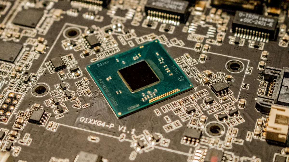
Integrated circuits combine many active and passive components on a single silicon chip. Each integrated circuit may contain thousands or millions of transistors, diodes, resistors, and capacitors. These components work together to perform complex tasks such as amplification, computation, and signal processing. Integrated circuits appear in almost every modern pcb, from microprocessors to audio amplifiers.
| Type of Integrated Circuit | Common Applications | Key Features |
|---|---|---|
| Digital | Computers, smartphones, controllers | Data processing, logic operations |
| Analog | Audio amplifiers, sensors | Signal amplification, filtering |
| Mixed-signal | Communication devices, IoT | Combines analog and digital signals |
The global market for integrated circuits continues to grow rapidly. In 2024, the semiconductor segment holds over half of the market share, with integrated circuits driving innovation in automotive, healthcare, and 5G infrastructure. Collaboration between industry leaders accelerates the development of smart platforms, increasing demand for these pcb components.
Integrated circuits rely on careful design for power management and signal integrity. Proper placement of these components on a pcb ensures reliable performance and supports advanced device functions. Technicians and engineers must understand how each integrated circuit interacts with other pcb components to achieve optimal results.
Other Key Components
Transformers
Transformers serve as essential pcb components that transfer electrical energy between circuits. They change voltage levels, making them vital for both safety and efficiency. In many pcb designs, transformers step down high voltage from power lines to levels suitable for household or device use. These components often appear as large, block-shaped parts with wire windings visible. Designers assign the letter "T" followed by a number to identify transformers on a pcb. Transformers support a wide range of applications, including power supplies and audio systems.
Relays
Relays act as electrically operated switches in pcb circuits. These components allow a low-power signal to control a higher power circuit. Relays use an internal coil and mechanical contacts to open or close circuits. On a pcb, relays appear as rectangular or square components, sometimes with transparent covers showing the internal mechanism. The designator "K" or "RY" helps identify relays among other pcb components. Relays find use in motor control, automation, and safety systems.
Connectors
Connectors provide the physical interface for connecting different pcb sections or external devices. These components come in many shapes and sizes, such as pin headers, sockets, and edge connectors. Connectors ensure reliable electrical contact and allow for easy assembly or replacement of pcb modules. Designers use the letter "J" or "P" to label connectors on a pcb. Common applications include data transfer, power delivery, and signal routing between pcb components.
Crystals and Oscillators
Crystals and oscillators generate precise timing signals for pcb circuits. Quartz crystals vibrate at a fixed frequency when voltage is applied, producing stable clock signals. Oscillators combine crystals with electronic circuits to create continuous waveforms. These components appear as small metal cans or cylinders on a pcb. The designator "Y" or "X" identifies crystals and oscillators. Microcontrollers, clocks, and communication devices rely on these pcb components for accurate timing and synchronization.
Fuses and Protection
Fuses and protection components safeguard pcb circuits from damage. Fuses provide one-time over-current protection by melting when current exceeds safe levels. Resettable fuses, such as PolySwitch devices, automatically restore the circuit after the fault clears. Designers also use metal oxide varistors (MOV), transient voltage suppression diodes (TVS), and gas discharge tubes to protect against voltage spikes and surges. These components carry the designator "F" on a pcb. Protection components play a crucial role in preventing failures and extending the life of pcb assemblies.
-
Common protection components in pcb designs:
-
Fuses and resettable fuses
-
MOV and TVS diodes
-
Gas discharge tubes and spark gaps
-
Circuit breakers and ground-fault devices
-
Tip: Always check the reference designators and markings to identify protection components on a pcb. Proper identification ensures safe and reliable operation in all applications.
Identifying Electronic Components on a PCB
Surface Mount vs. Through-Hole
Identifying electronic components on a pcb starts with recognizing the mounting technology. Surface mount technology (SMT) and through-hole technology (THT) represent the two main ways to attach components to a printed circuit board. Each method has unique features that help with identification.
Surface mount components sit directly on the surface of the pcb. They do not have long leads that pass through holes. Instead, their small metal contacts rest on flat pads. These components often appear much smaller than through-hole parts. SMT allows for higher component density and supports double-sided assembly. Manufacturers use automated machines to place and solder these parts, which makes SMT ideal for mass production.
Through-hole components have long leads that pass through holes in the pcb. These leads get soldered on the opposite side of the board. Through-hole parts are usually larger and easier to handle. They work well for prototyping and applications that need strong mechanical connections. Manual soldering is common with through-hole components, making them popular among hobbyists.
The table below highlights key differences between SMT and THT:
| Characteristic | Through Hole Technology (THT) | Surface Mount Technology (SMT) |
|---|---|---|
| Component Mounting | Leads inserted into plated holes | Leads attached to surface pads |
| Assembly | Manual or automated, easy hand soldering | Automated assembly and soldering |
| Component Spacing | Larger lead spacing | Much smaller lead spacing |
| PCB Layers | 2-sided assembly rare | 2-sided assembly common |
| Soldering Process | No stencil required | Stencil required for solder paste |
| Component Density | Lower density, larger footprint | Higher density, smaller footprint |
| Rework | Simple | More involved |
| Mechanical Robustness | More resilient to stress | Less resilient to stress |
| Suitability | Good for prototyping, high stress | Best for high-density, automated use |
When identifying electronic components, look for these clues:
-
SMT parts are smaller and may be mounted on both sides of the pcb.
-
Through-hole parts have visible leads going through the board.
-
SMT allows for more components in a smaller space.
-
Through-hole parts often support higher power and mechanical strength.
Tip: Use a magnifier to inspect the pcb. SMT parts often have tiny markings, while through-hole parts have larger bodies and visible leads.
Choosing between SMT and THT depends on the application. SMT works best for compact, high-volume products. Through-hole suits prototypes, repairs, and devices exposed to vibration or stress. Understanding these differences helps with identification and guides decisions about how to place pcb components and how to solder pcb parts.
Using Schematics and Datasheets
Schematics and datasheets serve as essential tools for identifying electronic components on a pcb. A schematic diagram shows the electrical connections and symbols for each component. Each symbol has a reference designator, such as R for resistor or C for capacitor. These codes match the markings on the printed circuit board, making identification easier.
The table below lists common reference designators and their component types:
| Reference Designator | Component Type |
|---|---|
| R | Resistor |
| C | Capacitor |
| L | Inductor |
| D | Diode |
| Q | Transistor |
| IC, U | Integrated Circuit |
| K | Relay |
| T | Transformer |
| F | Fuse |
| POT, VR | Potentiometer |
When identifying electronic components, follow these steps:
-
Locate the reference designator on the pcb.
-
Match the designator to the schematic symbol.
-
Read the part number printed on the component.
-
Search for the datasheet using the part number.
Datasheets provide detailed information about each component. They include pin layouts, electrical ratings, and recommended soldering methods. Manuals and online resources also help with identification. By using schematics and datasheets, technicians can confirm the function, orientation, and placement of each part.
Note: Always check the schematic and datasheet before replacing or soldering components. This ensures correct identification and prevents errors during assembly.
Schematics and datasheets also help with how to place pcb components. They show the correct orientation and connection points. This information supports accurate soldering and reliable operation. Identifying electronic components becomes much easier with these resources. Beginners and experienced technicians both rely on them for troubleshooting and repair.
Understanding the differences between SMT and THT, along with using schematics and datasheets, builds strong skills in identifying electronic components. These methods improve accuracy, speed up repairs, and support the long-term reliability of any pcb.
Component Classification and Connections
Grouping Components
Effective grouping of components forms the foundation of successful circuit board design. Logical grouping simplifies routing and reduces assembly errors. Designers often place high-speed components close together to minimize trace lengths and signal delay. Power components require strategic placement for optimal thermal dissipation and current flow. Consistent orientation and clear labeling of components help assembly teams avoid mistakes.
Design for Manufacturability (DFM) and Design for Assembly (DFA) principles guide how to choose pcb components and their arrangement. Maintaining proper spacing between components ensures compliance with design rule checks. Early collaboration with manufacturers helps identify potential issues before production begins. Grouping components by function, such as separating analog and digital sections, improves signal integrity and reduces interference. These practices support a reliable pcb and streamline testing and repair.
Tip: When learning how to purchase pcb components, consider their size, footprint, and compatibility with the intended grouping in your circuit board design.
PCB Connections
Reliable pcb connections ensure that electrical signals travel efficiently between components. Designers select connection types based on design complexity, cost, and signal integrity needs. Through-hole, blind, buried, and micro-vias each serve different applications. Careful via selection supports robust electrical connections and meets the demands of modern circuit board design.
Uninterrupted ground planes and optimized power distribution networks enhance signal integrity. High-speed signals often require routing as differential pairs with equal trace lengths. Controlled impedance routing, with precise trace width and spacing, maintains signal quality in high-frequency applications. Designers define pcb stack-up with dedicated ground and power planes to reduce crosstalk and impedance issues.
Testing forms a critical part of ensuring reliable pcb connections. Automated Optical Inspection (AOI), electrical testing, X-ray inspection, and functional testing verify the quality of electrical connections. Board bring-up involves checking hardware functionality and testing individual modules before full integration. These steps guarantee that all connections meet the requirements of the circuit board design.
Note: When considering how to choose pcb components or how to purchase pcb components, always review datasheets for connection requirements and compatibility with your design.
Accurate identification of pcb components ensures reliable circuit board performance and supports effective soldering. Comprehensive studies show that precise identification and inspection methods, including advanced deep learning, improve pcb quality and guide further learning. Practicing with real pcb assemblies helps users recognize components, refine soldering skills, and understand how each part affects operation. Soldering techniques, such as proper pad heating and controlled solder flow, prevent defects and extend pcb lifespan. Exploring hands-on projects, reviewing inspection techniques, and studying pcb schematics allow learners to master identification and soldering. These steps build confidence and expertise in pcb assembly and repair.
FAQ
What is the most important step in identifying pcb components?
Technicians start by visually inspecting the pcb. They look for unique shapes, markings, and reference designators. This step helps them quickly recognize resistors, capacitors, and other parts. Accurate identification prevents mistakes during repair or assembly.
How can someone tell if a pcb component is faulty?
They check for physical damage, such as burns or cracks, on the pcb. Testing with a multimeter helps confirm if a component works. Comparing the suspected part with the schematic also reveals faults. Proper diagnosis ensures the pcb functions correctly.
Why do some pcb components have polarity markings?
Polarity markings show the correct orientation for installation. Components like diodes and electrolytic capacitors need proper alignment to work. Incorrect placement on the pcb can cause failure or damage. Technicians always check polarity before soldering.
What tools help with pcb component identification?
A magnifying glass or microscope helps technicians see small pcb parts. Multimeters test electrical properties. Schematics and datasheets provide detailed information. These tools make it easier to identify and replace pcb components accurately.
Can someone replace a pcb component without a schematic?
They can replace simple pcb parts by matching reference designators and markings. However, using a schematic ensures correct placement and orientation. For complex pcb repairs, the schematic helps avoid errors and improves reliability.
Written by Jack from AIChipLink.
AIChipLink, one of the fastest-growing global independent electronic components distributors in the world, offers millions of products from thousands of manufacturers, and many of our in-stock parts is available to ship same day.
We mainly source and distribute integrated circuit (IC) products of brands such as Broadcom, Microchip, Texas Instruments, Infineon, NXP, Analog Devices, Qualcomm, Intel, etc., which are widely used in communication & network, telecom, industrial control, new energy and automotive electronics.
Empowered by AI, Linked to the Future. Get started on AIChipLink.com and submit your RFQ online today!


